807/ATS25
|
807/ATS25 |
|
|---|---|
|
|
|
| Classification: | Beam-Power Tetrode |
| Service: |
Class A amplifier, (Single-Ended) Class AB1 amplifier, (Push-Pull) |
|
Cathode |
|
| Cathode type: | Indirectly heated |
| Heater voltage: | 6.3 |
| Heater current: | 900mA |
|
Anode |
|
| Max dissipation Watts: | 25 watts |
| Max voltage: | 600 volts |
|
Socket Connections |
|
|
Anerican 5 Pin, (UY) Pin 1, Heater |
|
|
Typical Class A amplifier Operation |
|
| Anode voltage: | 300v, (600v) |
| Anode current: | 83mA, (40-75mA) |
| Screen voltage: | 250v, (300v) |
| Bias voltage: | -12.5v, (-29.5v) |
| Anode resistance: | 24K Ohms |
|
Typical Class C amplifier Operation |
|
| Power Output: | 24 watts, (Plate Dissipation = 16.5w max) |
| Anode voltage: | 475v |
| Anode current: | 83 mA |
| Screen voltage: | 300v (Screen Dissipation = 2.5w max) |
| Bias voltage: | -50v |
|
Typical Class AB amplifier Operation |
|
| Anode voltage: | 400v(AB1),600v(AB2) |
| Anode current: | 90-119mA(AB1), 90-240mA(AB2),(Zero to Max Signal) |
| Screen voltage: | 300v(AB1), 300v(AB2) |
| Bias voltage: | -45v(AB1), -25–30v(AB2) |
|
Reference |
|
|
Philips Valve Data Book, Philips Electrical Industries, 69-73 Clarence Street Sydney, Radio Valve Application Division, 1958 Radio Valve Data, Eighth Ed. Ilife Books Ltd., London, 1966 |
|
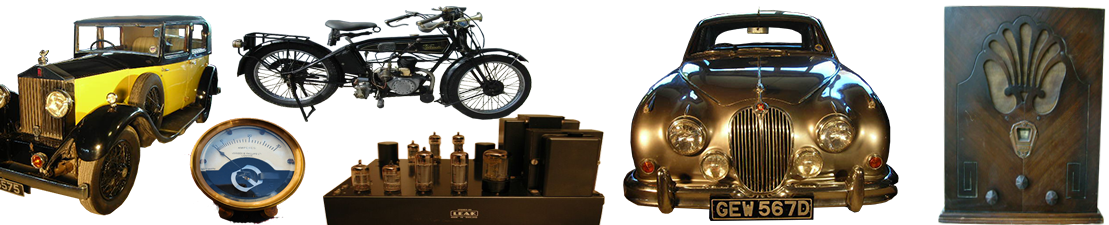
The 807 is a beam tetrode vacuum tube, widely used in AF and RF power amplifier applications. The 807 is one of the most ubiquitous and recognizable of thermionic valves/vacuum tubes.
Audio Uses
807s found use in audio power amplifiers, both for public address and “hi-fi” application, usually being run in push-pull pairs in class AB1 or AB2 giving up to 120 watts of usable power. Less commonly a single 807 could be seen in a pure class-A, “single-ended” audio output stage, but the power obtained was below 10 watts.
R.F. Uses
The 807 produces usable gain up to around 30MHz or so, thus they were popular with amateur radio operators (radio hams). In this application a single 807 could be run class-A or C as an oscillator which could be “keyed” on and off to transmit Morse Code in CW mode. For voice transmission on AM a “final” amplifier consisting of either a single 807 or multiple 807s, (up to about four), could be connected in parallel running class-C. Connecting multiple 807s in parallel produced more power to feed to the antenna. Often the modulator stage (simply a transformer-coupled audio amplifier for A.M., with the secondary of its output transformer in series with the anode supply of the “final”), was also constructed using 807s. Many hams found multiple paralleled 807s a cheaper alternative to a single larger valve, such as a single 813, as many military surplus 807s became available cheaply after World War II. In Australia 807s are affectionately referred to as “stubbies” because they are almost as ubiquitous as that common Australian beer container.
The class C operational values in the info box at the right are for anode modulated A.M. operation; for CW operation a maximum anode voltage of 600 is permissible, whereby the anode current increases to 100mA and the anode/plate dissipation rises to 25 watts. The screen voltage is the same, at 300, but its dissipation rises to 3.5 watts. 37 watts of R.F. power is produced from 220mW of drive but only a 50% duty cycle is allowed. The maximum allowable negative control grid, g1 excursion allowable is -200 volts and average control grid current is 5mA in both A.M. and CW modes.

Three 807s and an early 6L6,
Left, British Emitron brand 807
Second Left, Canadian Westinghouse brand 807
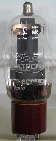
Second Right, Dutch Philips brand military 807/ATS25
Right, U.S. Mullard-B.V.A branded 6L6G
Differences from 6L6
The electrically similar 6L6 was not favored by hams because high transient voltages on the anode when operating in class C could cause a “flashover” between pins 2 and 3 on the octal base, whereas the 807 had the anode connected to a top cap, electrically distant from all the base pins.
In guitar amplifiers, this flashover problem sometimes occurs if the amplifier is operated without the speakers connected, whereby the self inductance of the output transformer primary winding can generate high voltages when the current changes due to the applied signal. For this reason the speaker terminals of tube amplifiers are sometimes short-circuited by a switching 6.5mm jack when the speakers are disconnected.
Derivatives
The 1624 (VT-165) is an 807 variant with a directly heated filamentary cathode operating at 2.5V, 2A.
The 1625 (VT-136) is an 807 variant with a 12.6V heater and a 7-pin base. These tubes were used as RF power amplifiers in some of the SCR-274 and AN/ARC-5 “command set” transmitters of WW2. Postwar, 1625 tubes flooded the surplus market, and were available for pennies apiece. Surplus 1625s found some commercial use, notably the use of a pair as modulator tubes in the Heathkit DX-100 amateur transmitter.
The 5933/807W is a ruggedized military version of the 807. It uses a shorter, straight-sided T12 bulb, which provides better element support for improved microphonics and shock/vibration resistance.
The 807 also found some use as a horizontal output tube in early TV receivers, particularly those manufactured by DuMont. The 807 design (with some “value engineering” to reduce production cost) was the basis for the first application-specific horizontal sweep tubes such as the 6BG6G and 6CD6G. The redesign mainly involved the omission of some of the internal RF shielding, and the substitution of a bakelite octal base for the micanol or ceramic 5-pin.
In turn, these low cost sweep tube derivatives found some use as RF power amplifiers in homebrew amateur radio transmitters in the 1950s.